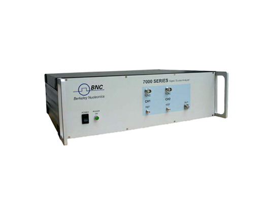


The 7000 series is an integrated solution that offers an indispensable set of measurement functions for evaluating VHF to microwave frequency signal sources such as crystal oscillators, PLL synthesizers, clocks, phase-locked or free-running VCO's, DROs, SAW, or Yig oscillators, and others. The flexible instrument comprises a two-channel, cross-correlation system with two internal, tunable references sources that also allows measurements with externally sourced references. We offer three platform options for the 7000 Series Phase Noise Testers: the 7070 5 MHz-to-7 GHz, the 7300 5 MHz-to-26 GHz, and the 7340 from 5 MHz-to-40 GHz.
Absolute and residual phase noise measurements
Amplitude noise measurements
PULSED absolute and residual phase noise measurements
Two channel 100 MHz FFT analyzer
Transient measurements (frequency, Phase, Amplitude versus time)
Oscillator test bench (tuning, pushing, phase noise, current, power etc.)
Spectrum Analysis
Frequency counter function / power meter
Broad Frequency Range in a single compact instrument from 5 MHz to 40 GHzMeasurement offest from .01 Hz to 100 MhzDedicated High Drift Mode ( ability to measure modulations, high drifting or unstable DUTs, etc)AM (Absolute Amplitude Noise) measurements
Two Independent Internal Low Noise power supplies includedPulsed Measurement CapabilitiesUltra-low noise internal reference or external references for measurements down to -188 dBc/Hz
Absolute Phase Noise Measurement 5 MHz to 40 GHz (CW)
Measurement parameters
SSB phase noise [dBc/Hz], Spurious noise [dBc],
Integrated rms phase deviation [deg, rad] or time jitter [s],
Residual FM/PM [Hz rms]
7000 20G RF Frequency Range 7070 7300-26 7340-40G
FMIN
5 MHz
5 MHz
5 MHz
FMAX
7 GHz
26 GHz
40 GHz
using internal/external references internal references internal references
Input Power Range
to 2 GHz
2 to 9 GHz
9 to 18 GHz
18 to 30 GHz
30 to 40 GHz
-15 dBm
-12 dBm
-10 dBm
-13 dBm
0 dBm
+17 dBm
+20 dBm
+20 dBm
+20 dBm
+23 dBm
+26 dBm is damage level
See also RF sensitivity plot
Input impedance
VSWR
50 Ω
2
AC coupled, 10V DC max
Offset Analysis Range
Resolution
0.01 Hz
2
100 MHz
3800
points per decade, RBW adjustable
Measurement Accuracy
±4 dB
±3 dB
±2 dB
< 10 Hz offset
< 1 kHz offset
>1 kHz
System Phase Noise Floor (100 MHz)
1 Hz
10 Hz
100 Hz
1 kHz
10 kHz
10 MHz
-140 dBc/Hz
-150 dBc/Hz
-160 dBc/Hz
-175 dBc/Hz
-188 dBc/Hz
-188 dBc/Hz
(cross-correlation, external references)
Phase Noise Sensitivity
See plot for sensitivity of internal sources
Spurious levels
External References
Internal references
-85 dBc
-90 dBc
Measurement time
See Table “Measurement Time”
Trigger
Single, continuous, manual, bus
Internal References Cross-correlation
Frequency Range 1 MHz FMAX
Phase Noise Sensitivity See Plots “Sensitivity”
RF Tracking Range ±1 ppm ±10 ppm >±1000 ppm Option LN Standard High drift mode
External References One or Cross-correlation
Frequency Range 5 MHz 18 GHz
RF Input Level Range < 10 GHz > 10 GHz +10 dBm +13 dBm +23 dBm +23 dBm +26 dBm is damage level
Reference Level Range +13 dBm +17 dBm + 21 dBm
Tuning Voltage Range -5 V +20 V User adjustable
Output current >20 mA